Hardware
This section details the physical and electrical aspects of the iW-ST-StarterKit (Rev. RV01), based on the product datasheet.
Board overview
The iW-ST-StarterKit is a compact, low-cost devkit built around the STM32F030F4P6 (ARM Cortex-M0, up to 48 MHz). It integrates everything needed to program and debug without external hardware: USB-C, a USB-Serial bridge, an on-board regulator, ESD protection and dedicated buttons.
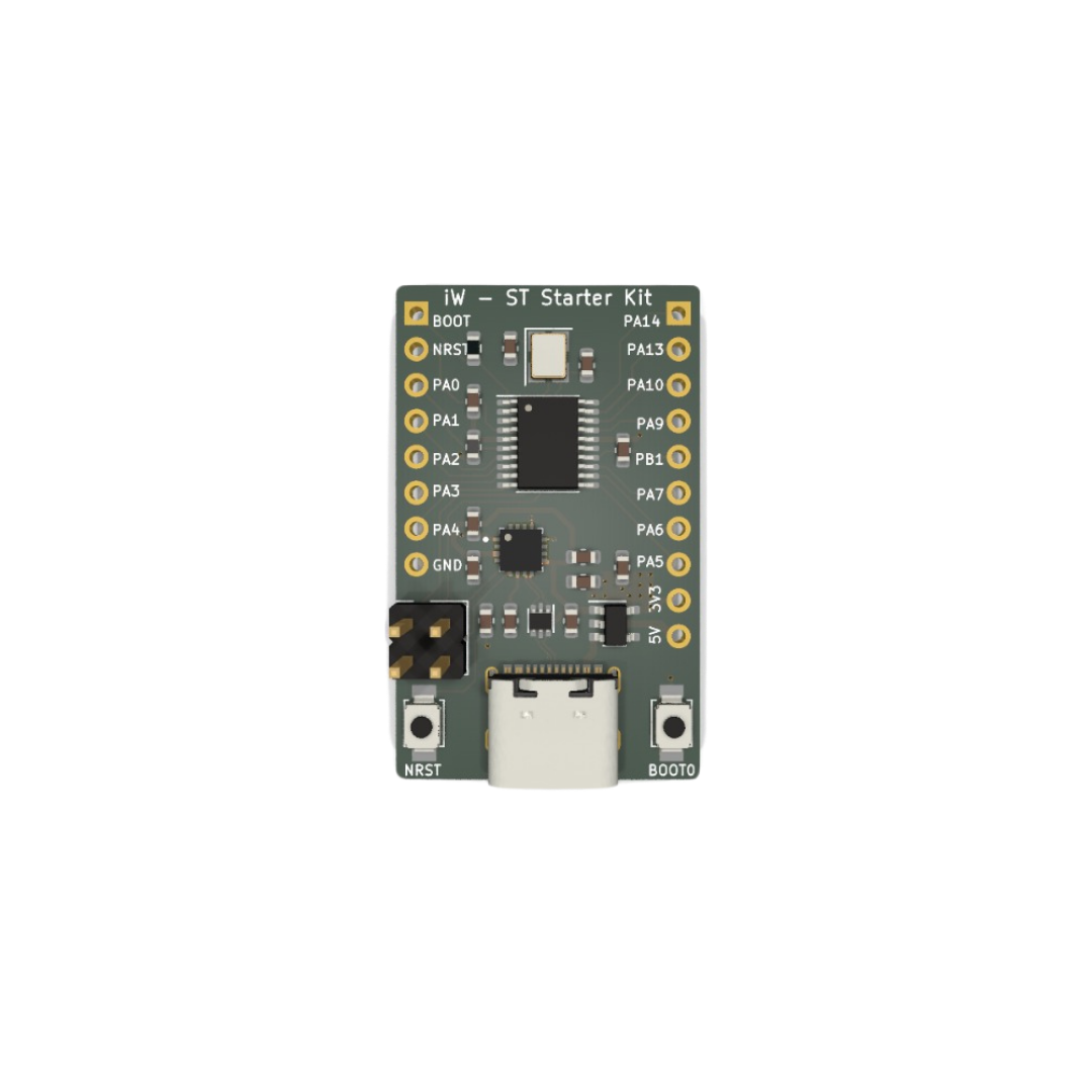
3D model
Drag to rotate, scroll to zoom.
Main features
STM32F030F4P6MCU (Cortex-M0, up to 48 MHz, TSSOP-20)- 16 KB of Flash + 4 KB of SRAM
- USB-C connector with
USBLC6-2P6ESD protection CH343Pserial bridge (USB to UART / USART1)AP2112K-3.3LDO regulator (5 V to 3.3 V, up to 600 mA)- 20 MHz external crystal (22 pF load capacitors)
- Programming via SWD (PA13/PA14) and serial bootloader via BOOT0
- Up to 15 multifunction GPIOs on the expansion connectors
Electrical specifications
| Parameter | Min. | Typ. | Max. | Unit / Notes |
|---|---|---|---|---|
| USB input voltage (V_BUS) | 4.5 | 5.0 | 5.5 | V — USB-C connector |
| System logic voltage | — | 3.3 | — | V — generated by the AP2112K |
| Max. regulator current | — | — | 600 | mA — AP2112K-3.3 |
| CPU clock frequency | — | — | 48 | MHz |
| External crystal frequency | — | 20 | — | MHz |
| MCU operating voltage | 2.4 | 3.3 | 3.6 | V — STM32F030F4 |
| Typical consumption (Run, 48 MHz) | — | ~12 | — | mA |
| Stop-mode consumption | — | ~5 | — | uA |
| Operating temperature | -40 | — | +85 | °C |
Consumption figures are typical for the STM32F030F4 and vary with firmware, clock and active peripherals.
Power management
Power comes from the USB-C connector (5 V). The AP2112K-3.3 LDO converts the 5 V into a stable 3.3 V for the MCU and peripherals. Both the 3.3 V and 5 V rails are also available on the expansion connectors.
| Resource | Description |
|---|---|
| Power input | USB-C (5 V via V_BUS) |
| Regulation | AP2112K-3.3 LDO — 3.3 V output up to 600 mA |
| Decoupling | 100 nF / 10 uF capacitors on the 5 V and 3.3 V rails |
| Analog filtering | Ferrite bead (600R) + 100 nF on the MCU VDDA pin |
| Available outputs | 3V3 and 5V pins on the expansion connectors |
Peripherals and interfaces
USB-Serial bridge — CH343P
A USB-to-UART converter that connects the STM32 USART1 (PA9/TX and PA10/RX) directly to the computer over USB-C, enabling serial communication, debug logging and programming via the bootloader without an external adapter.
Debug — SWD
Pins PA13 (SWDIO) and PA14 (SWCLK) expose the Serial Wire Debug interface for programming and debugging with tools such as ST-Link. Available on the expansion connector.
ESD protection — USBLC6-2P6
A dedicated component protecting against electrostatic discharge on the USB-C D+/D- data lines.
Pin map / expansion connectors
The board exposes the STM32F030F4P6 GPIOs on two side connectors. Most pins are multifunction (GPIO, ADC, I2C, SPI, USART, timers and PWM).
| Pin | Signal | Alternate functions | Notes |
|---|---|---|---|
| 1 | PA0 | ADC_IN0, USART2_CTS, TIM2_CH1 | analog input / wakeup |
| 2 | PA1 | ADC_IN1, USART2_RTS, TIM2_CH2 | analog input |
| 3 | PA2 | ADC_IN2, USART2_TX, TIM2_CH3 | analog input / UART |
| 4 | PA3 | ADC_IN3, USART2_RX, TIM2_CH4 | analog input / UART |
| 5 | PA4 | ADC_IN4, SPI1_NSS | analog input / SPI |
| 6 | PA5 | ADC_IN5, SPI1_SCK | analog input / SPI |
| 7 | PA6 | ADC_IN6, SPI1_MISO, TIM3_CH1 | analog input / SPI |
| 8 | PA7 | ADC_IN7, SPI1_MOSI, TIM3_CH2 | analog input / SPI |
| 9 | PB1 | ADC_IN9, TIM3_CH4 | analog input |
| 10 | PA9 | USART1_TX, I2C1_SCL | UART1 TX -> CH343P |
| 11 | PA10 | USART1_RX, I2C1_SDA | UART1 RX -> CH343P |
| 12 | PA13 | SWDIO | SWD debug |
| 13 | PA14 | SWCLK | SWD debug |
| 14 | 3V3 | — | regulated 3.3 V output |
| 15 | 5V | — | 5 V input/output (USB-C V_BUS) |
| 16 | GND | — | reference / ground |
PA13/PA14are the SWD interface by default — reconfigure them as GPIO only if you are not using debugging. The numbering follows the silkscreen of the side connectors.
Buttons and controls
| Button | Signal | Function |
|---|---|---|
| NRST | NRST | resets the STM32F030 microcontroller |
| BOOT0 | BOOT0 | enters the system bootloader (serial programming) on reset |
Online schematic
View the hardware project directly in your browser:
Mechanical and environmental information
| Item | Specification |
|---|---|
| Main connector | USB-C (power + data) |
| Expansion connectors | side headers, 2.54 mm pitch |
| Microcontroller | STM32F030F4P6 — TSSOP-20 |
| Operating temperature | -40 °C to +85 °C |
| Logic voltage | 3.3 V |