Hardware
This page details the hardware blocks of the iW-Scott (Rev. RV01), based on the product datasheet.
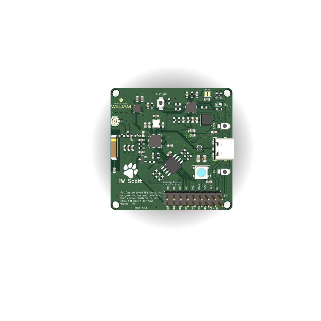
3D model
Drag to rotate, scroll to zoom.
Board overview
The iW-Scott is a compact, low-power Development Board Tools built around the ESP32-C3 SoC (RISC-V, single-core, up to 160 MHz) with Wi-Fi and Bluetooth 5 LE. It brings together intelligent power management, an accelerometer, an addressable RGB LED and external flash memory in a single module.
Main features
ESP32-C3SoC (RISC-V 32-bit, up to 160 MHz)- SoC internal memory: 400 KB SRAM, 384 KB ROM, 4 MB flash
- Winbond
W25Qexternal QSPI flash — 8 MB or 16 MB - Wi-Fi 802.11 b/g/n 2.4 GHz + Bluetooth 5 LE / Mesh
- 3-axis
LIS3DHaccelerometer (I2C/SPI) - Addressable
WS2812BRGB LED (NeoPixel) PT1502PMIC (Li-ion charger, buck and LDOs)AN9520-245ceramic antenna and U.FL connector- 40 MHz crystal (22 pF load capacitors)
- USB-C with
USBLC6ESD protection
Electrical specifications
| Parameter | Min. | Typ. | Max. | Unit / Notes |
|---|---|---|---|---|
| USB input voltage (V_BUS) | 4.5 | 5.0 | 5.5 | V — USB-C connector |
| Battery voltage (Li-ion) | 3.0 | 3.7 | 4.2 | V — single cell |
| System logic voltage | — | 3.3 | — | V — generated by the PT1502 |
| Battery charge current | — | — | ~1.0 | A — programmable (PT1502) |
| CPU clock frequency | — | — | 160 | MHz |
| Crystal frequency | — | 40 | — | MHz |
| Active-mode consumption (Wi-Fi TX) | — | ~280 | — | mA (transmission peak) |
| Modem-sleep consumption | — | ~20 | — | mA |
| Deep-sleep consumption | — | ~5 | — | uA |
| Operating temperature | -40 | — | +85 | °C |
Consumption figures are typical for the ESP32-C3 and vary with firmware, RF power and active peripherals. The charge current depends on the PT1502 resistor configuration and the battery capacity.
Power management (PMIC PT1502)
The power circuit revolves around the PT1502, which integrates a Li-ion charger, a buck converter (2.2 uH inductor) and LDOs. It automatically selects between USB (5 V) and battery, generating the system's 3.3 V rail.
| Resource | Description |
|---|---|
| Power inputs | USB-C (5 V via V_BUS) and Li-ion battery |
| Charging | integrated Li-ion charger, with LED status (CHG_STAT) |
| Outputs | regulated buck + LDOs for 3.3 V and auxiliary rails |
| Monitoring | BAT_LEVEL divider to read battery voltage via ADC; BAT_LOW / CHG_PROG signals |
| Control | PLAY_ON, uP_RESET and PWR_HOLD signals for power on/off |
Integrated peripherals
Accelerometer — LIS3DH
An ultra-low-power 3-axis inertial sensor (I2C and SPI), ideal for motion detection, orientation, gestures and TinyML. Connected to the ESP32-C3 SDA/SCL/CS lines.
RGB LED — WS2812B
An addressable LED (NeoPixel) controlled by a single data pin (DIN line), driven by the U0TXD/GPIO21 line. It enables colored status signaling over a 1-wire serial protocol.
QSPI flash memory — W25Q
External Winbond serial flash, in 8 MB (W25Q64) or 16 MB (W25Q128), over a QSPI bus (CS/CLK/IO0-IO3) for firmware, ML models, file systems and data.
Pin map / expansion connector (2x9)
The board exposes the ESP32-C3 GPIOs on an 18-pin double connector. Most pins are multifunction (GPIO, ADC1, I2C, SPI, UART and software PWM).
| Pin | Signal | Alternate functions | Notes |
|---|---|---|---|
| 1 | GPIO0 | ADC1_CH0, XTAL_32K_P | analog input |
| 2 | GPIO1 | ADC1_CH1, XTAL_32K_N | analog input |
| 3 | GPIO2 | ADC1_CH2 | strapping / boot pull-up (4.7 k) |
| 4 | GPIO3 | ADC1_CH3 | analog input |
| 5 | GPIO4 | ADC1_CH4, MTMS | JTAG / ADC |
| 6 | GPIO5 | ADC2_CH0, MTDI | JTAG / ADC |
| 7 | GPIO6 | MTCK | GPIO / JTAG |
| 8 | GPIO7 | MTDO | GPIO / JTAG |
| 9 | GPIO8 | — | strapping; boot pull-up (4.7 k) |
| 10 | GPIO9 | BOOT | strapping; BOOT button (download) |
| 11 | GPIO10 | PLAY_ON | power-on control |
| 12 | GPIO20 | U0RXD | UART0 (console) — RX |
| 13 | GPIO21 | U0TXD | UART0 (console) — TX; -> WS2812B LED |
| 14 | 3V3 | — | regulated 3.3 V output |
| 15 | GND | — | reference / ground |
| 16 | GND | — | reference / ground |
| 17 | BATT | — | Li-ion battery voltage (3.0-4.2 V) |
| 18 | 5V | — | 5 V input/output (USB-C V_BUS) |
GPIO2,GPIO8andGPIO9are strapping pins — mind the level constraints during boot. The numbering follows the 2x9 expansion connector (J4).
Buttons and controls
| Button | Signal | Function |
|---|---|---|
| RESET (EN) | ESP_EN | resets the ESP32-C3 (via a BC807 transistor) |
| BOOT | GPIO9 | enters download / programming mode on reset |
| PLAY / ON | GPIO10 / PLAY_ON | power-on and power control (PT1502) |
Connectivity
- Wi-Fi for local-network and IoT integration
- Bluetooth 5 LE / Mesh for apps, beacons and BLE peripherals
- on-board ceramic antenna with a U.FL option for an external antenna
- GPIOs available for expansion and additional peripherals
Online schematic
View the hardware project directly in your browser:
Versions
| Variant | External QSPI flash | Recommended use |
|---|---|---|
| iW-Scott / 8 MB | Winbond W25Q64 (8 MB) | standard IoT firmware, OTA, file systems |
| iW-Scott / 16 MB | Winbond W25Q128 (16 MB) | larger ML models, extensive logging, multi-OTA |
Mechanical and environmental information
| Item | Specification |
|---|---|
| Main connector | USB-C (power + data) |
| Expansion connector | 2x9 header (18 pins), 2.54 mm pitch |
| Battery | dedicated connectors for a single Li-ion cell |
| Operating temperature | -40 °C to +85 °C |
| Logic voltage | 3.3 V |