Hardware
This section describes the main physical and electrical aspects of the iW-ESPMI-IND.
Board overview
The iW-ESPMI-IND was designed for industrial applications with a strong need for communication and a visual interface.
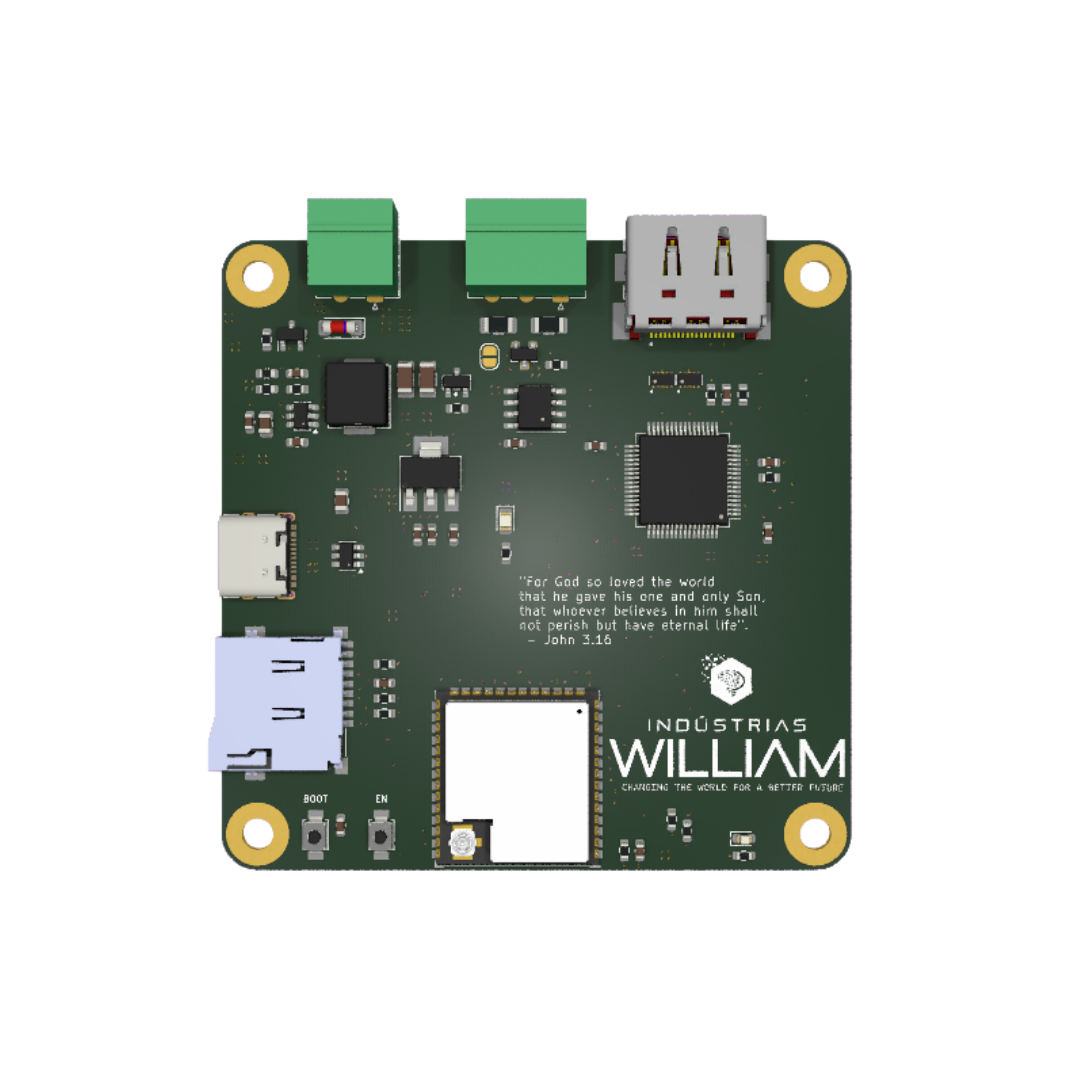
3D model
Drag to rotate, scroll to zoom.
Pinout
The image below summarizes the board's most important interfaces.
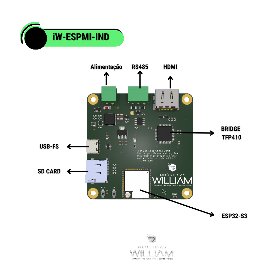
Main interfaces
- USB for programming and communication
- RS485 for a Modbus RTU network
- SD Card for local storage
- HDMI for video output
Power
The board supports a wide power range, which makes it easy to use in industrial scenarios. The input goes through polarity protection (AO3401A MOSFET + zener) before the power stage based on the LMR61430 converter, which establishes the 5 V rail (5VP). From there, the AMS1117-3.3 LDO generates the system's 3.3 V rail; an LED indicates the presence of the 3.3 V voltage.
| Resource | Description |
|---|---|
| Power input | screw terminal (J1) with reverse-polarity protection |
| Power stage | LMR61430 converter + 6.8 uH inductor -> 5 V rail (5VP) |
| 3.3 V regulator | AMS1117-3.3 LDO powering the logic and the ESP32-S3 |
| USB | USB-C V_BUS (5 V) tied to the 5VP rail |
| Indication | 3.3 V rail status LED |
Electrical specifications
| Parameter | Min. | Typ. | Max. | Unit / Notes |
|---|---|---|---|---|
| Input voltage (terminal) | 6.5 | — | 36 | V — power input |
| Intermediate rail (5VP) | — | 5.0 | — | V — power stage |
| System logic voltage | — | 3.3 | — | V — AMS1117-3.3 |
| USB voltage (V_BUS) | 4.5 | 5.0 | 5.5 | V — USB-C connector |
| CPU clock frequency | — | — | 240 | MHz |
| Video output | — | HDMI 1.4 | — | DVI/HDMI via TFP410 |
| RS485 termination | — | 120 | — | ohms — selectable via JP1 |
| I/O logic voltage | — | 3.3 | — | V |
| Operating temperature | -40 | — | +85 | °C — limited by the ESP32-S3 |
Use a stable power supply when the HDMI display, SD card and external loads are connected at the same time. The resolution / pixel-clock range of the HDMI output depends on the firmware configuration and the TFP410 limits.
Interfaces and resources
Video
- HDMI output
- a solid base for interfaces with LVGL and visual tools
Industrial communication
- on-board RS485 transceiver
- good fit for Modbus RTU scenarios
Storage
- SD Card slot for logs, assets and configurations
Online schematic
View the hardware project directly in your browser:
Best practices
- use a stable power supply in the field
- mind the grounding in RS485 networks
- keep power and data cables well separated
- validate dissipation and noise in industrial installations