Hardware
This section details the physical and electrical aspects of the iW-AIoT-eXplorer (Rev. RV01), based on the product datasheet.
Board view
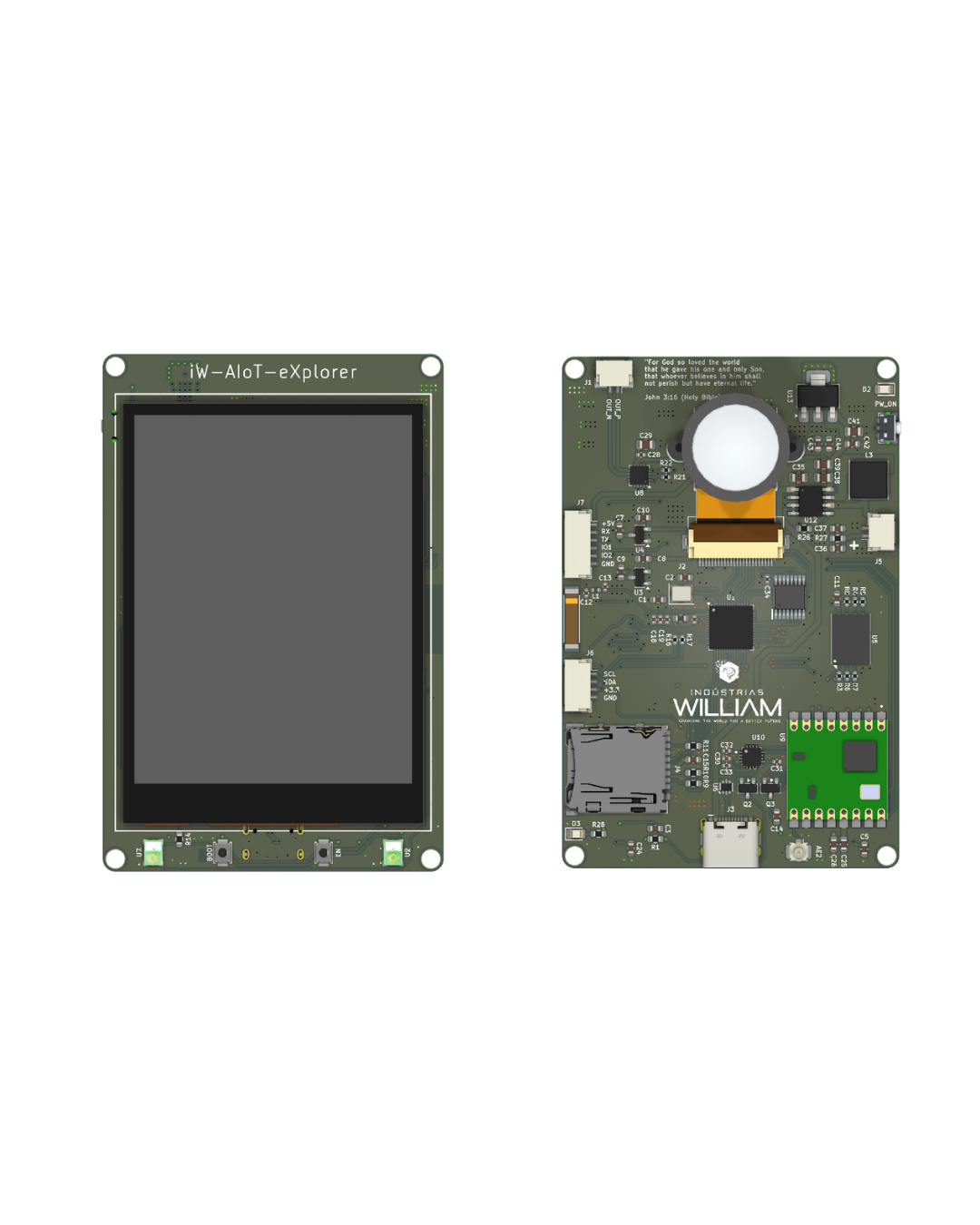
Component identification
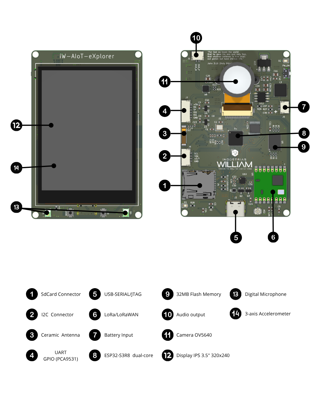
The front face has the 3.5" IPS display with capacitive touch; on the back are the OV5640 camera, the ESP32-S3R8 SoC, the flash memory, the LoRa module and the expansion connectors.
3D model
Interactive board model. Drag to rotate, scroll to zoom, and use two fingers (or the right mouse button) to pan. Click the gizmo axes (bottom-right corner) to align the camera with each view.
Main features
ESP32-S3R8SoC (Xtensa LX7 dual-core, up to 240 MHz) with vector instructions for AI/ML- 8 MB of Octal SPI PSRAM integrated in the package (R8 suffix)
- 16 MB (
W25Q128) or 32 MB (W25Q256) external QSPI flash - Wi-Fi 802.11 b/g/n + Bluetooth 5 LE / Mesh (2.4 GHz)
- LoRa / LoRaWAN
RFM95W-915S2(SX1276), 915 MHz (AU915/US915) OV5640camera — DVP 8-bit + SCCB (I2C)- 2x PDM digital microphones
IMP34DT05(stereo L/R) - Class-D I2S audio
MAX98357A+ speaker connector - 3.5" 320x240 IPS display
ST7789(SPI) with capacitive I2C touch - 3-axis
LIS3DHaccelerometer (I2C) Hirose DM3ATmicroSD in SPI mode- I2C I/O expander
PCA9531(backlight, resets, UART mux, GPIOs) - USB-C with
CH343PUSB-Serial bridge and automatic boot/reset IP5306PMIC (Li-ion charging + 5 V boost) andAMS1117-3.3LDO
Electrical specifications
| Parameter | Min. | Typ. | Max. | Unit / Notes |
|---|---|---|---|---|
| USB input voltage (V_BUS) | 4.5 | 5.0 | 5.5 | V — USB-C connector |
| Battery voltage (Li-ion) | 3.0 | 3.7 | 4.2 | V — single cell |
| Boost rail (IP5306) | — | 5.0 | — | V — IP5306 VOUT |
| System logic voltage | — | 3.3 | — | V — AMS1117-3.3 LDO |
| CPU clock frequency | — | — | 240 | MHz |
| Crystal frequency | — | 40 | — | MHz (20 pF load cap.) |
| Integrated PSRAM | — | 8 | — | MB — Octal SPI (R8) |
| External QSPI flash | 16 | — | 32 | MB — W25Q128 / W25Q256 |
| LoRa frequency | — | 915 | — | MHz (AU915 / US915) |
| Typical consumption (Wi-Fi active) | — | ~250 | — | mA (RF peak) |
| Deep-sleep consumption | — | ~10 | — | uA (peripherals off) |
| Operating temperature | -40 | — | +85 | °C |
Consumption figures are typical for the ESP32-S3 and vary with firmware, RF power, active peripherals (camera, display, audio) and backlight brightness.
Power management (PMIC IP5306 + LDO)
The power system combines the IP5306 — a Li-ion charger, a synchronous boost converter (1 uH inductor) and button management with LED level indication — with the AMS1117-3.3 regulator that generates the 3.3 V logic rail.
| Resource | Description |
|---|---|
| Power inputs | USB-C (5 V via V_BUS) and Li-ion battery (J5 connector) |
| Charging | Li-ion charger integrated in the IP5306, with current sensing |
| Boost / 5 V output | IP5306 synchronous boost converter (L3 1 uH) generates the 5 V rail |
| 3.3 V rail | AMS1117-3.3 LDO from the 5 V; power-indicator LED |
| Battery indication | charge-level LEDs driven by the IP5306 |
| Button control | KEY button (SW3) for power on/off and energy management |
Integrated peripherals
Camera — OmniVision OV5640
A 5 MP CMOS sensor (2592x1944, 1/4") with on-board autofocus, AEC/AGC and AWB, connected over an 8-bit DVP parallel interface and configured via the SCCB bus (I2C-compatible). The main clock (MCLK) comes from a dedicated oscillator, and the analog (2.8 V) and core (1.2 V) domains are generated by local LDOs.
| Parameter | Value | Notes |
|---|---|---|
| Sensor | OmniVision OV5640 | CMOS, 1/4" optical format |
| Max. resolution | 5 MP — 2592x1944 | QSXGA |
| Frame rates | QSXGA 15 fps · 1080p 30 fps · 720p 60 fps | VGA 90 fps · QVGA 120 fps |
| Output formats | RGB565/555/444, YUV422/420, RAW, JPEG | — |
| Data interface | 8-bit parallel DVP | PCLK / HSYNC / VSYNC + CSI_D0-D7 |
| Control | SCCB (I2C-compatible) | SIO_C / SIO_D |
| Features | autofocus, AEC, AGC, AWB | embedded MCU and AF motor |
The 4 least-significant bits of the camera bus (
CSI_D0-D3) are multiplexed with the LoRaDIO0-DIO3lines by theQS3257QG, selected byGPIO9(0 = LoRa, 1 = camera). So camera and radio-event reception operate alternately.
Digital microphones — 2x IMP34DT05
Two MEMS PDM microphones from STMicroelectronics in a stereo arrangement (L/R channels set by the LR pin), sharing the PDM_CLK / PDM_DOUT lines. Omnidirectional and low-power, ideal for keyword spotting, sound classification and beamforming.
| Parameter | Value |
|---|---|
| Configuration | stereo (L / R) over a single data line |
| SNR | 64 dB |
| Sensitivity | -26 dBFS +/-3 dB |
| AOP | 122.5 dB SPL |
| PDM clock | 1.2 – 3.25 MHz |
| Power | 3.3 V |
Audio output — MAX98357A
A filterless Class-D I2S amplifier that receives digital audio directly from the ESP32-S3 (BCLK/LRCLK/DIN), dispensing with an external DAC and MCLK, and drives a speaker through the dedicated connector (J1) in a bridge (BTL) configuration.
| Parameter | Value | Notes |
|---|---|---|
| Max. output power | 3.2 W | 4 ohm load · 5 V · THD+N 10% |
| Efficiency | up to 92% | Class-D |
| THD+N | 0.013% | 1 kHz typical |
| Gain | 3 / 6 / 9 / 12 / 15 dB | selectable; 9 dB default |
| Load | 4 – 8 ohms | 4 ohms for max power |
| Sample rates | 8 – 96 kHz | I2S, no MCLK |
3.5" IPS display + touch — ST7789
A 3.5" 320x240 IPS display with the ST7789 controller over SPI; the backlight is switched by an AO3400A MOSFET, with control (on/off and PWM) by the PCA9531 expander. The capacitive touch uses its own I2C interface (interrupt on GPIO6).
| Parameter | Value | Notes |
|---|---|---|
| Type | TFT LCD IPS | wide viewing angle |
| Resolution | 320x240 | QVGA (landscape) |
| Controller | Sitronix ST7789 | integrated GRAM |
| Interface | 4-wire SPI | SCLK / MOSI / MISO / CS / DC / RST |
| Backlight | LED via AO3400A MOSFET | control and PWM by the PCA9531 |
| Touch | capacitive · I2C | INT on GPIO6; SDA/SCL on the I2C bus |
Accelerometer — LIS3DH
An ultra-low-power 3-axis MEMS sensor over I2C (INT1/INT2 interrupts), with selectable full scales, an internal FIFO and embedded motion-detection functions.
| Parameter | Value |
|---|---|
| Full scales | +/-2 / +/-4 / +/-8 / +/-16 g |
| Resolution | 16 bits per axis |
| Data rate (ODR) | 1 Hz – 5.3 kHz |
| Consumption | ~2 uA – 11 uA |
| Interrupts | INT1 / INT2 (motion, click, free fall, 4D/6D) |
| Features | 32-level FIFO, aux. ADC, temperature sensor |
LoRa / LoRaWAN — RFM95W-915S2
A radio module based on the Semtech SX1276, at 915 MHz, with an SPI interface (shared with the microSD), DIO0-DIO2 interrupt lines and a dedicated antenna. The hardware implements the LoRa physical layer; LoRaWAN (classes A/B/C) is enabled by software.
| Parameter | Value | Notes |
|---|---|---|
| Module / chip | RFM95W-915S2 · SX1276 | sub-GHz LoRa transceiver |
| Band | 915 MHz | AU915 / US915 (ISM) |
| Modulation | LoRa (CSS), (G)FSK, OOK | — |
| Max. output power | +20 dBm (100 mW) | via PA_BOOST |
| RX sensitivity | down to -148 dBm | depending on SF and bandwidth |
| TX consumption | ~120 mA @ +20 dBm | ~87 mA @ +17 dBm |
| RX consumption | ~10.3 mA | continuous reception |
| Sleep consumption | ~0.2 uA | radio in sleep |
Storage — microSD (Hirose DM3AT)
A push-push microSD socket in SPI mode, with 10 k pull-ups, sharing the SPI bus with the LoRa module (independent chip-selects). Typically with a FAT16/FAT32 file system for images, ML models, datasets and logs.
I/O expander — PCA9531
An 8-output (open-drain) I2C expander/dimmer that centralizes auxiliary signals, freeing up ESP32-S3 GPIOs.
| Output | Signal | Function |
|---|---|---|
| LED0 | BACKLIGHT | display backlight on/off and brightness PWM |
| LED1 | LCD_RST | ST7789 controller reset |
| LED2 | Auxiliary control | reserved line |
| LED3 | S1 | UART mux selection (HEF4052) |
| LED4 | S2 | UART mux selection (HEF4052) |
| LED5 | OUT1 | general-purpose output (expansion connector) |
| LED6 | OUT2 | general-purpose output (expansion connector) |
| LED7 | L_RST | LoRa module reset (RFM95W) |
USB-Serial — CH343P
A USB-Serial converter (WCH CH343P) connected to the USB-C, with automatic reset/boot via DTR/RTS (through BC817 transistors) driving EN (reset) and GPIO0 (boot) — flashing without pressing buttons. The UART can be routed between the CH343P and the external connector by the HEF4052 mux (S1/S2 selection via the PCA9531).
GPIO allocation map (ESP32-S3)
| GPIO(s) | Signal | Interface | Notes |
|---|---|---|---|
| 18 / 15 / 14 | SCLK / MOSI / MISO | SPI | ST7789 display SPI bus |
| 16 / 17 | CS / DC | SPI | display chip-select and Data/Command |
| 11 / 12 / 10 | SCLK / MOSI / MISO | SPI | shared microSD + LoRa bus |
| 13 / 21 | CS_SD / NSS_LoRa | SPI | microSD and LoRa module selectors |
| 5 / 19 | SCL / SDA | I2C | touch, LIS3DH, PCA9531 and connector (2.2 k pull-up) |
| 6 | TOUCH_INT | I2C | capacitive touch panel interrupt |
| 7 / 8 / 4 | BCLK / LRCLK / DIN | I2S | audio to the MAX98357A |
| 20 / 3 | PDM_CLK / PDM_DOUT | PDM | digital microphones (GPIO3 is strapping) |
| 40 / 42 / 45 / 46 | CSI_D4-D7 | DVP | 4 most-significant bits — direct to the ESP32-S3 |
| 38 / 39 / 47 / 48 | CSI_D0-D3 / DIO0-D3 | DVP / LoRa | camera 4 LSB multiplexed with LoRa DIO0-3 (QS3257QG) |
| 9 | MUX_SEL | Control | QS3257QG selection — 0 = LoRa (DIO), 1 = camera (CSI_D0-3) |
| 1 / 2 / 41 | PCLK / HSYNC / VSYNC | DVP | sync; SCCB (SIO_C/SIO_D) on its own bus |
| 0 | BOOT | Strapping | BOOT button (download mode) |
| CHIP_PU | RESET | — | RESET button (resets the ESP32-S3) |
GPIO0,GPIO3,GPIO45andGPIO46are ESP32-S3 strapping pins — mind the level constraints during boot. Camera and LoRa share GPIOs 38/39/47/48 through theQS3257QG, driven byGPIO9, operating alternately.
Buttons and controls
| Button | Signal | Function |
|---|---|---|
| RESET | CHIP_PU | resets the ESP32-S3R8 |
| BOOT | GPIO0 | enters download / programming mode on reset |
| KEY / ON | SW3 (IP5306) | power on/off and energy management by the PMIC |
Online schematic
View the hardware project directly in your browser:
Versions
| Variant | External QSPI flash | Recommended use |
|---|---|---|
| iW-AIoT-eXplorer / 16 MB | Winbond W25Q128 (16 MB) | standard AIoT firmware, OTA, compact ML models |
| iW-AIoT-eXplorer / 32 MB | Winbond W25Q256 (32 MB) | larger vision/audio models, datasets in flash, multi-OTA |
Mechanical and environmental information
| Item | Specification |
|---|---|
| Display | IPS 3.5" · 320x240 · ST7789 · capacitive I2C touch |
| Main connector | USB-C (power + data, via CH343P) |
| Camera | flex connector for the OV5640 module (DVP + SCCB) |
| Storage | microSD socket with detection (Hirose DM3AT) |
| Audio | speaker connector (J1, 2 ways) |
| Battery | connector for a single Li-ion cell (J5, 2 ways) |
| I2C expansion | dedicated I2C connector (SDA / SCL / 3.3 V / GND) |
| UART/GPIO expansion | connector with UART and GPIO via the PCA9531 |
| Antennas | AN9520-245 ceramic (2.4 GHz) + dedicated LoRa 915 MHz antenna |
| Operating temperature | -40 °C to +85 °C |
| Logic voltage | 3.3 V |